

R: Sí, pero se requieren estrategias de control de arena y resistencia al desgaste: filtros/rectificadores de entrada, componentes de válvulas con caras duras, holguras y tratamientos de superficie optimizados y ciclos de revisión de válvulas más cortos.
Q5: ¿Existe un método rápido para calcular la producción?Utilice Q ≈ (π·D² / 4) · (S / (231×42)) · SPM · 1440 · ηvol para la estimación; ηvol requiere corrección dinámica basada en diagramas de potencia/pruebas de nivel de líquido.
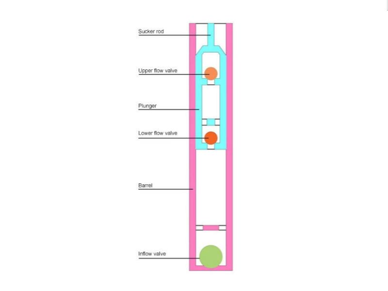
Differences between API tubing pumps and traditional sucker rod pumps:
Structural Position: The pump barrel is fixed to the tubing (API tubing pump) vs. the pump barrel is pulled and retracted with the rod (insert pump).
Pressure Capacity and Rigidity: API tubing pumps offer higher pressure resistance and are more stable in high-pressure and deep wells.
Maintenance Strategy: API tubing pumps have relatively higher maintenance costs but longer maintenance cycles.
2. Mechanisms of "Liquid Shock" and "Gas Interference":
Liquid shock: Alternating gas-liquid/slug flow enters the pump chamber. The combined effects of instantaneous valve opening and closing and fluid inertia create pressure spikes that impact valve components and the plunger-barrel mating surfaces, causing premature wear, failure, and downtime.
Gas interference/gas lock: High GLR at the pump inlet causes aeration in the pump chamber, leading to compression rather than displacement, resulting in a "liquid-free stroke" and a significant decrease in pump efficiency.
Impact on API tubing pumps: In deep wells, high pressures, and high GLR applications, failure to address gas/liquid shock can easily lead to valve shock, plunger strain, efficiency fluctuations, and frequent pump shutdowns.
3. Operating Principle and Design of API tubing pumps:
Thick-walled barrel + precise clearances: Maintain concentricity and sealing under high pressure, reducing leakage.
Fixed installation: The barrel does not reciprocate with the rod, resulting in high structural rigidity and improved resistance to uneven wear. Valve Manifold Matching: The opening and closing characteristics, materials, and elastic components of the station/travel valves are matched to the impact environment.
Optional Buffer Structure: In high-surge conditions, a buffer chamber or throttling element can be added to reduce pressure gradients.
Material and Surface: Corrosion-resistant (H₂S/CO₂), wear-resistant (sand-containing), and temperature-resistant (high-temperature well) materials—combined with surface treatments (such as hardening/plating) to extend service life.
4. API Tubing Pump Selection Calculation:
Goal: Given Q_target (target production), match pump diameter D, stroke S, stroke rate SPM, and volumetric efficiency η_vol.
Displacement and Production Estimation Formula (Imperial)
Displacement per stroke (bbl/str):
V_str = (π · D² / 4) · (S / (231 × 42))
Where D and S are in inches; 231 in³ = 1 gal, 42 gal = 1 bbl
Daily production (bpd):
Q ≈ V_str · SPM · 1440 · η_vol
Volumetric efficiency ηvol:
High GLR: ηvol↓, requiring the addition of an air anchor/gas separator or valve strategy modification.
High viscosity/high sand content: Increased valve hysteresis and leakage, ηvol↓.
Eccentric wear/poor concentricity: Increased clearance leads to leakage, ηvol↓.
Key points for selecting the diameter of an API tubing pump:
Prioritizing production: Small pump diameter + high stroke rate/long stroke vs. large pump diameter + low stroke rate. A comprehensive comparison of rod load, wear, and energy consumption is required. Tubing Fit: Match the tubing ID/OD to the pump's outer diameter, taking into account the lifting/lowering process and the space available for the sand control structure.
Dynamics: Stroke frequency and stroke affect rod string resonance and fatigue life. It is recommended to optimize the stroke frequency in conjunction with a variable frequency drive (VFD).
5. Operating Limits and Common Failure Modes of API Tubing Pumps:
Valve Impact/Liquid Surge: Characterized by valve seat erosion, valve plate damage, and spikes/distortion in the power diagram.
Gas Lock/Insufficient Inflating: Low pump fill, resulting in a "slender" power diagram and significant production fluctuations.
Eccentric Wear and Strain: Well deviation, eccentric wear, and sand particles cause longitudinal scratches on the plunger/pump barrel, increasing leakage.
Sand Sticking: Sand blocks the valve port or fitting clearance, causing pump sticking/intermittent failure.
Corrosion and Stress Cracking: H₂S/CO₂ + chloride ions + high-stress environments require coordinated materials and anti-corrosion strategies.
API tubing pump material/structural countermeasures:
Sand content: Hard-faced valves, throttling buffers, rational inlet flow regulation, and sand control screens/gravel packs.
Corrosion: Corrosion-resistant alloys/platings and corrosion inhibitors; seals should be made of heat-resistant and acid-resistant materials.
Eccentric wear: Centralizers/friction reducers, improved guides, and optimized stroke frequency to reduce lateral loads on the rod string.
6. Integration of API tubing pumps with "gas/liquid shock prevention" solutions:
Anti-gas: Downhole gas anchors/gas separators, two-stage plungers/specific valve timing design, and optimized upper/lower plunger diameter ratios.
Goal: Increase pump fill and suppress gas lock.
Anti-liquid shock: Buffer chambers/throttling, optimized valve elasticity, plunger quality and clearance ratios, and control pressure gradients.
Goal: Reduce transient shocks and extend the life of valve components and mating surfaces. On API tubing pumps, two technologies can be integrated in parallel: first "stabilizing gas flow" and then "reducing shock," typically significantly improving pump efficiency and lifespan.
7. On-site Monitoring and Diagnosis of API Tubing Pumps:
Dynamometer Diagrams: Determine pump fill, valve leakage, liquid spikes, and rod string load windows.
Liquid Level Logging/Wellhead Parameters: Estimate pump inlet pressure and GLR changes, dynamically correcting stroke rate and stroke utilization.
Energy Consumption and Stroke Rate Optimization: VFD + stroke time-sharing strategy avoids resonance zones and reduces rod string fatigue.
Fault Tree and Spare Parts Rotation: Develop common failures (valves, fit, corrosion, sand jamming) into a pattern-symptom-action SOP.
8. Quantitative Comparison of API Tubing Pumps with Other Artificial Lift Technologies:
Comparison with Insert Pumps: API tubing pumps excel in pressure resistance and stability; insert pumps offer easy maintenance and minimize well outage time. Compared to ESPs (Electric Submersible Pumps): ESPs are suitable for ultra-high production rates and high liquid volumes, but cable, frequency converter, and motor maintenance costs are high. API tubing pumps are more economical for medium-production deep wells.
Compared to PCPs (Progressive Cavity Pumps): PCPs are more stable in high-viscosity and solids-laden conditions, but are sensitive to elastic stator materials and temperature. API tubing pumps offer advantages in high-pressure/high-temperature compatibility and metal seal life.
9. FAQ:
Q1: How to choose an API tubing pump vs. an insert pump?
A: API tubing pumps are preferred for deep wells, high pressures, and large head differences. If the wellsite prioritizes rapid maintenance and downtime savings, insert pumps are more preferred. Prioritize target production and maintenance strategies, then evaluate materials and dynamic loads.
Q2: What should be done if high GLR results in low pump efficiency?
A: Place an air anchor/gas separator at the pump inlet. If necessary, use a two-stage plunger/specific valve timing design, combined with stroke optimization and liquid level monitoring, to improve fill rate and ηvol.
Q3: How can frequent liquid hammering be addressed? A: Introduce buffering/throttling and optimize elasticity in the valve manifold and pump body to reduce pressure spikes; simultaneously, suppress slugging through process technology (throttling, flow stabilizers, and reasonable pumping frequency).
Q4: Can API tubing pumps be used in sand-laden wells?
A: Yes, but sand control and wear resistance strategies are required: inlet screens/rectifiers, hard-faced valve components, optimized clearances and surface treatments, and shorter valve overhaul cycles.
Q5: Is there a quick method for calculating production?
Use Q ≈ (π·D² / 4) · (S / (231×42)) · SPM · 1440 · ηvol for estimation; ηvol requires dynamic correction based on power diagrams/liquid level testing.